Band Limited Signal
A
signal is said to be a band limited signal if all of its frequency components
are zero above a certain finite frequency. i.e it's power spectral density
should be zero above the finite frequency.
Figure 1 shows a signal g(t) that is band
limited.

Bandwidth
requirements (communications)
The channel bandwidths needed to transmit various types of
signals, using various processing schemes. Every signal observed in practice
can be expressed as a sum (discrete or over a frequency continuum) of
sinusoidal components of various frequencies. The plot of the amplitude versus
frequency constitutes one feature of the frequency spectrum (the other being
the phase versus frequency). The difference between the highest and the lowest
frequencies of the frequency components of significant amplitudes in the
spectrum is called the bandwidth of the signal, expressed in the unit of
frequency, hertz. Every communication medium (also called channel) is capable
of transmitting a frequency band (spectrum of frequencies) with reasonable
fidelity. Qualitatively speaking, the difference between the highest and the
lowest frequencies of components in the band over which the channel gain
remains reasonably constant (or within a specified variation) is called the channel
bandwidth.
Clearly, to transmit a signal with reasonable fidelity over a
communication channel, the channel bandwidth must match and be at least equal
to the signal bandwidth. Proper conditioning of a signal, such as modulation or
coding, however, can increase or decrease the bandwidth of the processed
signal. Thus, it is possible to transmit the information of a signal over a
channel of bandwidth larger or smaller than that of the original signal.
Amplitude modulation (AM) with double sidebands (DSB), for
example, doubles the signal bandwidth. If the audio signal to be transmitted
has a bandwidth of 5 kHz, the resulting AM signal bandwidth using DSB is 10
kHz. Amplitude modulation with a single sideband (SSB), on the other hand,
requires exactly the same bandwidth as that of the original signal. In
broadcast frequency modulation (FM), on the other hand, audio signal bandwidth
is 15 kHz (for high fidelity), but the corresponding frequency-modulated signal
bandwidth is 200 kHz.
C. E. Shannon proved that over a channel of bandwith B the
rate of information transmission, C, in bits/s (binary digits per
second) is given by the
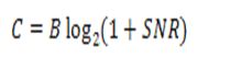
equation
below, where SNR is the signal-to-noise power ratio. This result assumes a
white Gaussian noise, which is the worst kind of noise from the point of view
of interference.
It follows from Shannon's equation that a given information
transmission rate C can be achieved by various combinations
of B and SNR. It is thus possible to trade B for
SNR, and vice versa.
A corollary of Shannon's equation is that, if a signal is
properly processed to increase its bandwidth, the processed signal becomes more
immune to interference or noise over the channel. This means that an increase
in transmission bandwidth (broadbanding) can suppress the noise in the received
signal, resulting in a better-quality signal (increased SNR) at the receiver.
Frequency modulation and pulse-code modulation are two examples of broadband
schemes where the transmission bandwidth can be increased as desired to suppress
noise.
Broadbanding is also used to make communication less vulnerable to
jamming and illicit reception by using the so-called spread spectrum signal.
Comments
Post a Comment